-
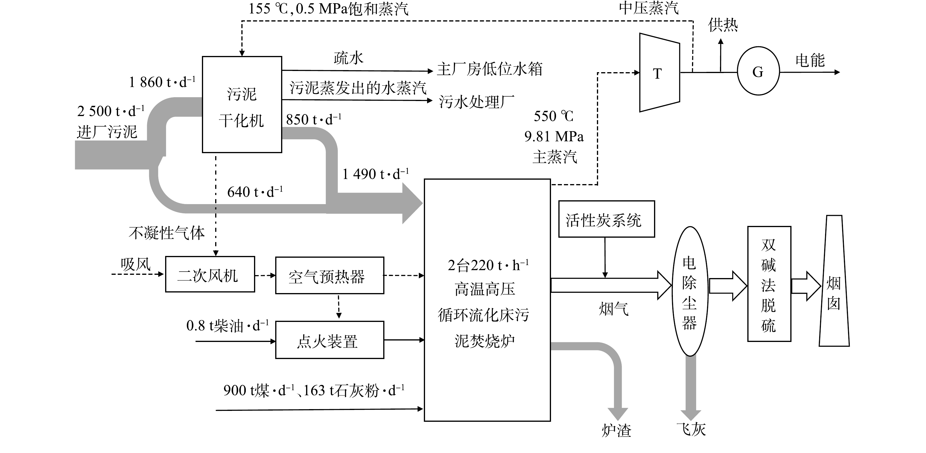
图 1 污泥能源化利用热电联产项目工艺流程图
Figure 1. Process flow chart of sludge energy utilization cogeneration project
-
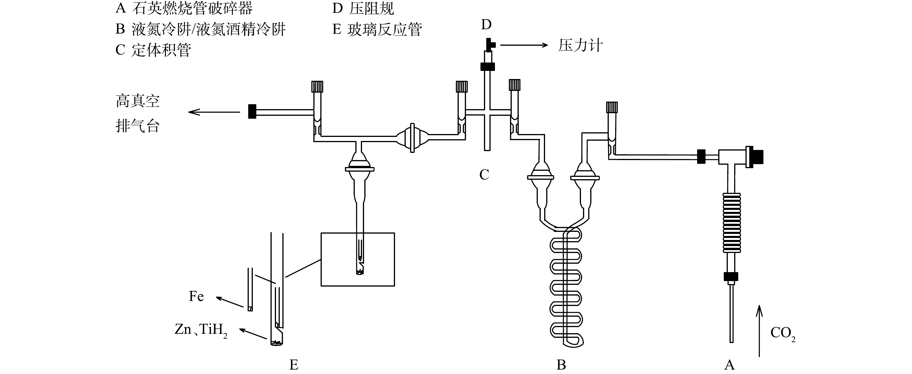
图 2 石墨制备实验台
Figure 2. Graphite preparation bench
-
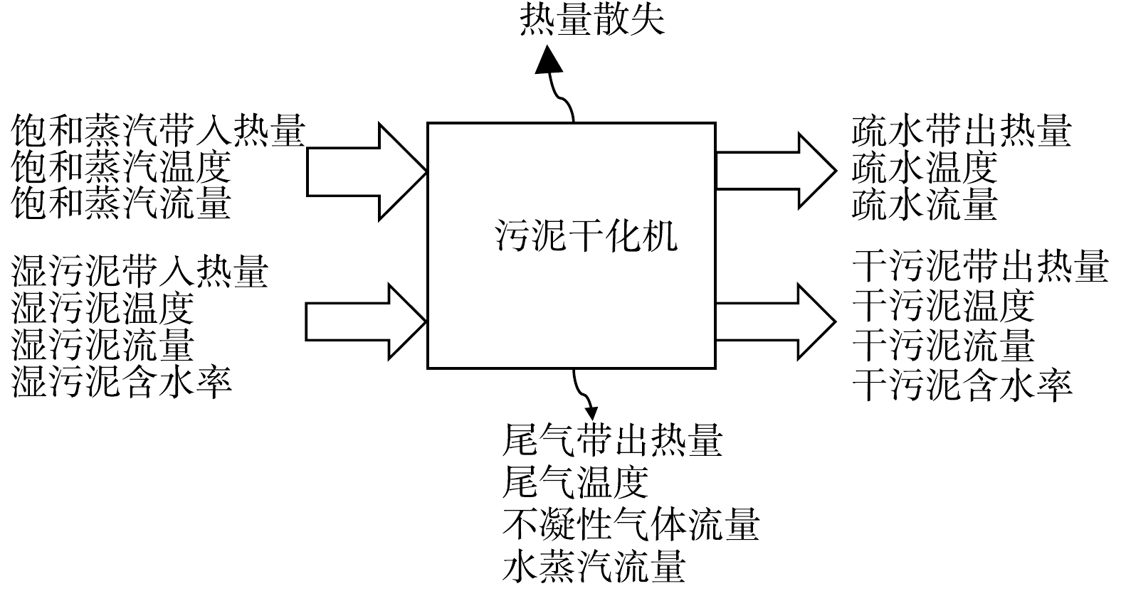
图 3 污泥干化机质量和能量平衡图
Figure 3. Mass and heat balance diagram of sludge dryer
-
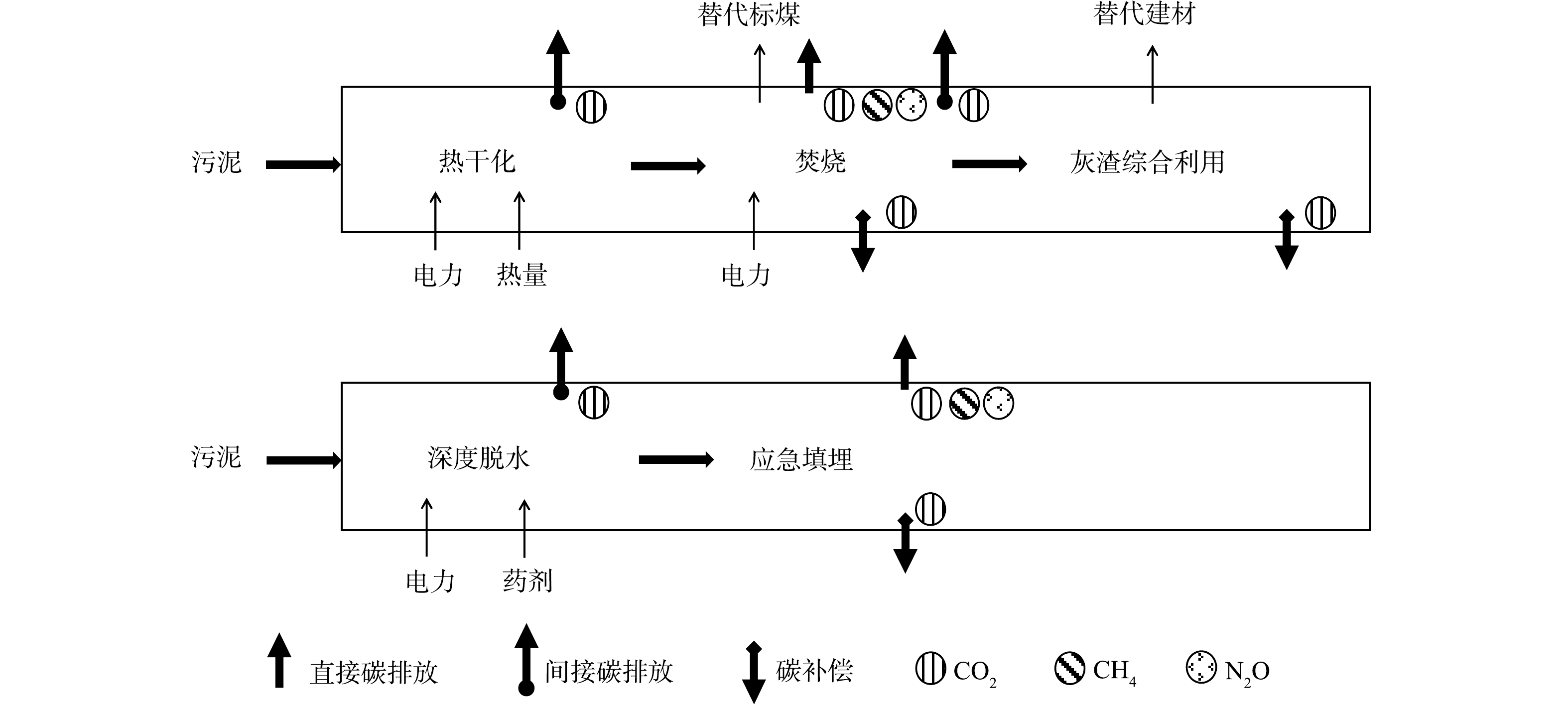
图 4 污泥两种处理处置路径的碳排放核算边界
Figure 4. Carbon emission accounting boundary of sludge two treatment and disposal paths
-
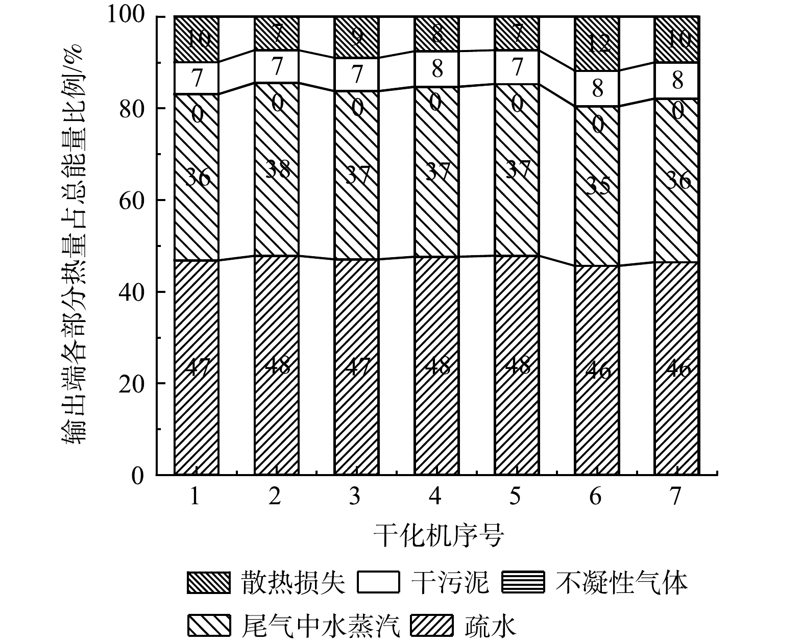
图 5 干化机输出端各部分热量占总能量比例
Figure 5. Ratio of heat from each section of sludge dryer's output to total energy
-

图 6 污泥干化焚烧-灰渣综合利用各环节碳排放因子
Figure 6. Carbon emission factors in each link of sludge drying incineration - comprehensive utilization of ash and slag path
-
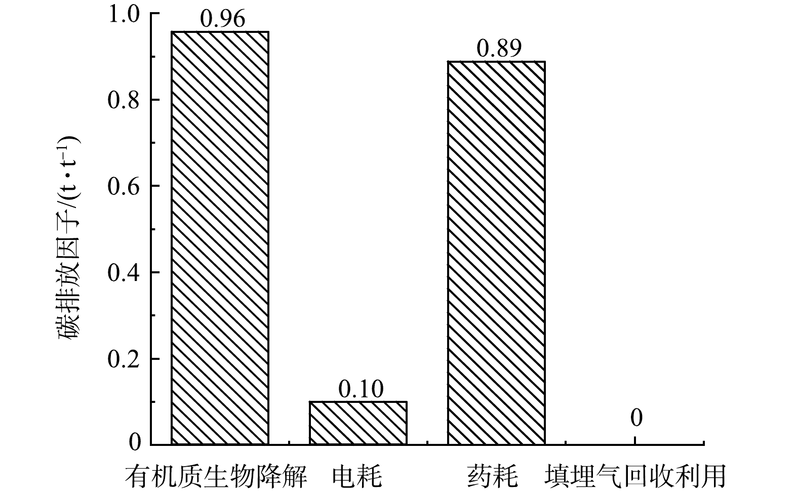
图 7 污泥深度脱水-应急填埋路径各环节碳排放因子
Figure 7. Carbon emission factors in each link of sludge deep dehydration - emergency landfill path
Figure
7 ,Table
9 个