-

图 1 微波催化燃烧VOCs实验装置示意图
Figure 1. Schematic diagram of the experimental device for microwave catalytic combustion of VOCs
-
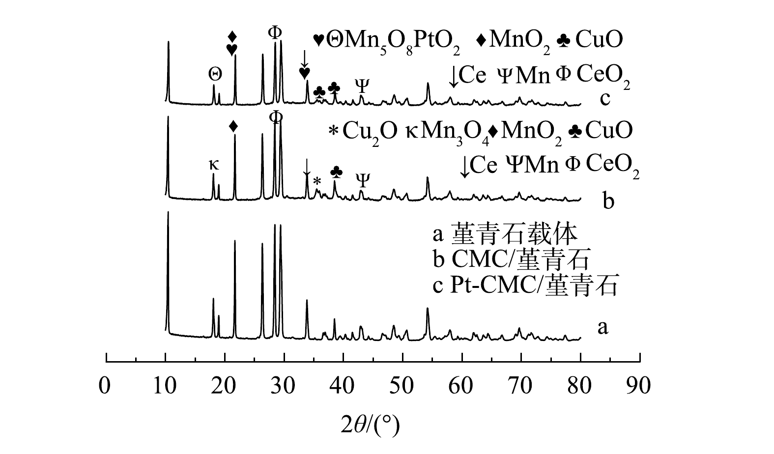
图 2 堇青石载体及CMC/堇青石、Pt-CMC/堇青石催化剂的XRD谱图
Figure 2. XRD spectra of Cordierite support and CMC/Cordierite and Pt-CMC/Cordierite catalysts
-

图 3 堇青石载体、CMC/堇青石与Pt-CMC/堇青石催化剂的微观表面形貌
Figure 3. Microscopic surface morphology of Cordierite, CMC/Cordierite and Pt-CMC/Cordierite catalyst
-
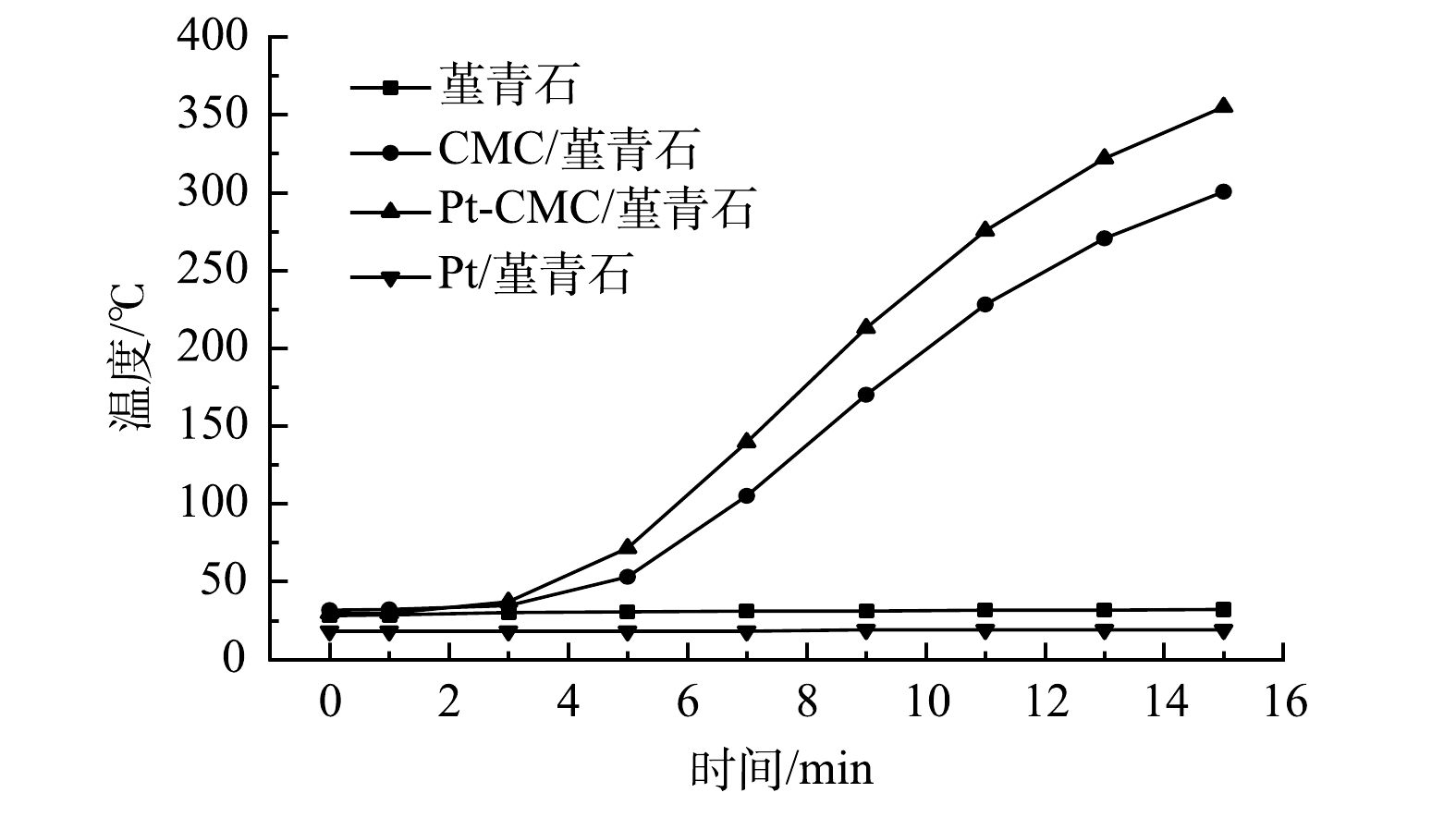
图 4 堇青石载体及3种催化剂的吸波升温曲线
Figure 4. Wave absorption heating curve of Cordierite and three catalysts
-
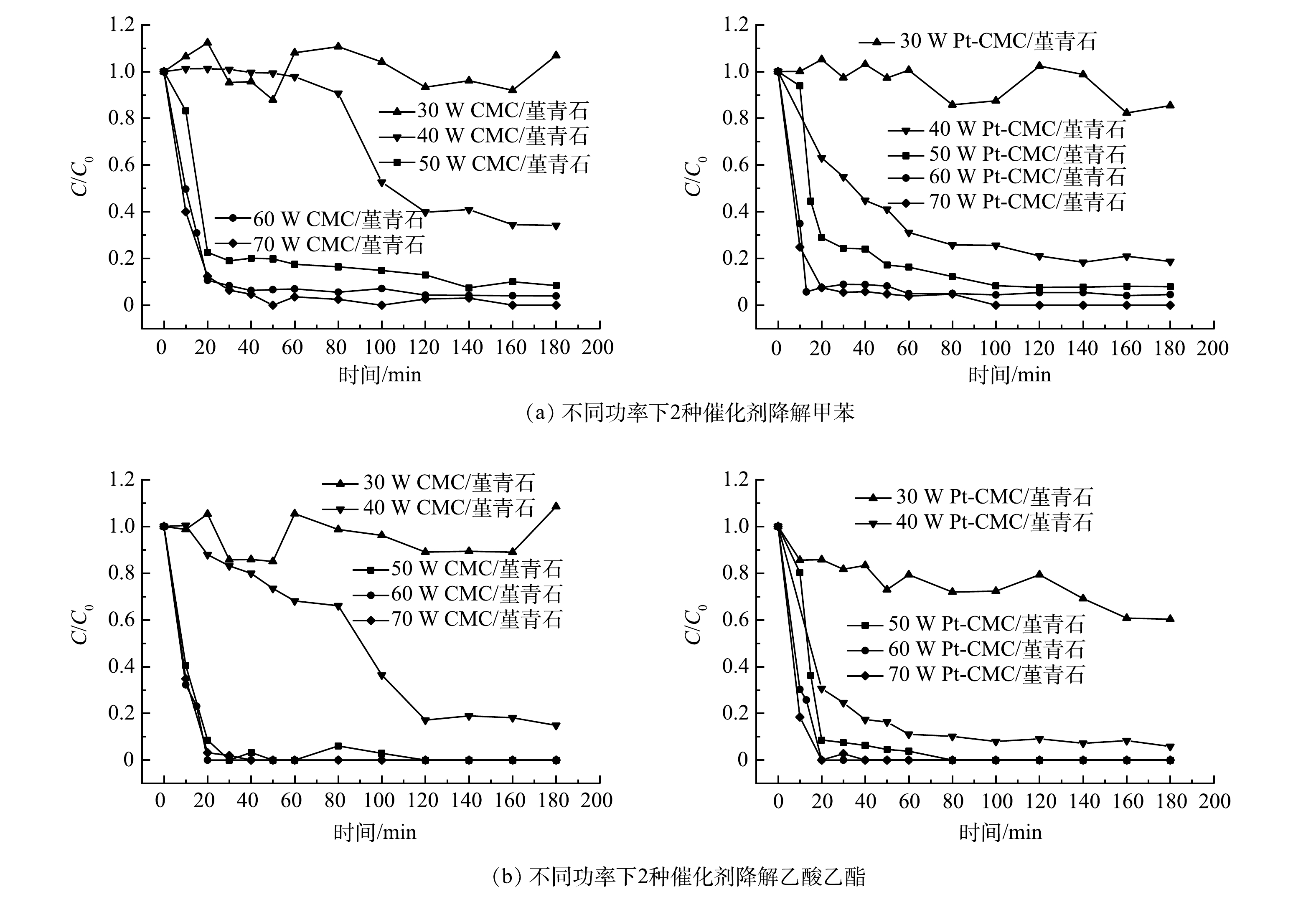
图 5 不同微波功率下CMC/堇青石和Pt-CMC/堇青石催化燃烧甲苯和乙酸乙酯效率曲线
Figure 5. CMC/Cordierite and Pt-CMC/Cordierite catalytic combustion efficiency curves of toluene and ethyl acetate under different microwave power
-
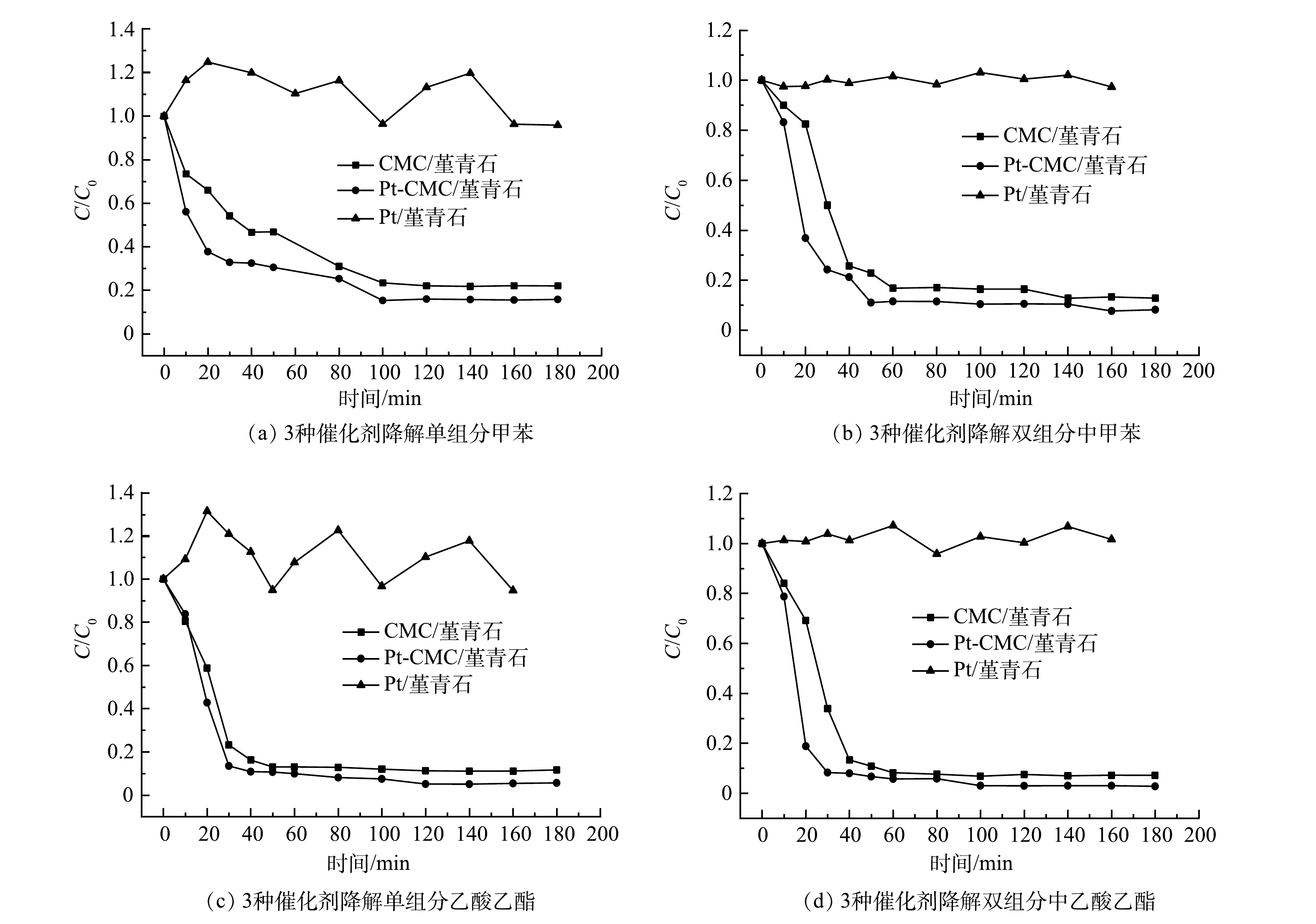
图 6 不同催化剂对甲苯和乙酸乙酯的催化活性比较
Figure 6. Comparison of catalytic activity of three catalysts to toluene and ethyl acetate
-
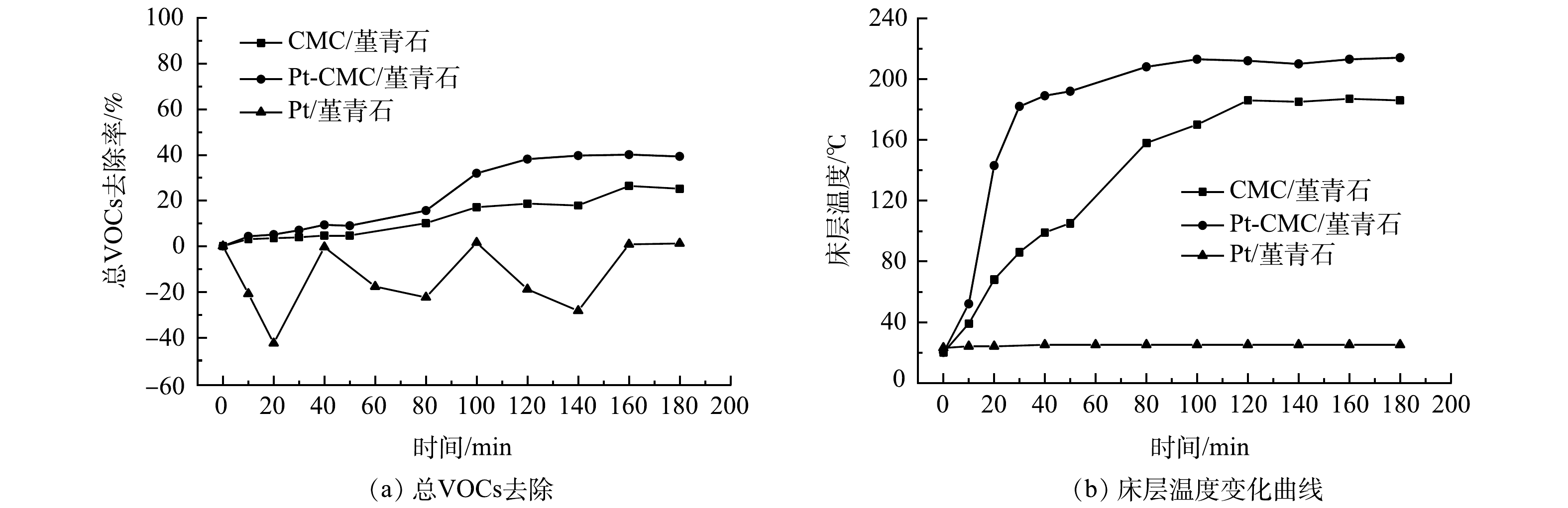
图 7 不同催化剂的总VOCs去除效率及床层温度曲线
Figure 7. The total VOCs removal efficiency and bed temperature curves of the three catalysts
-
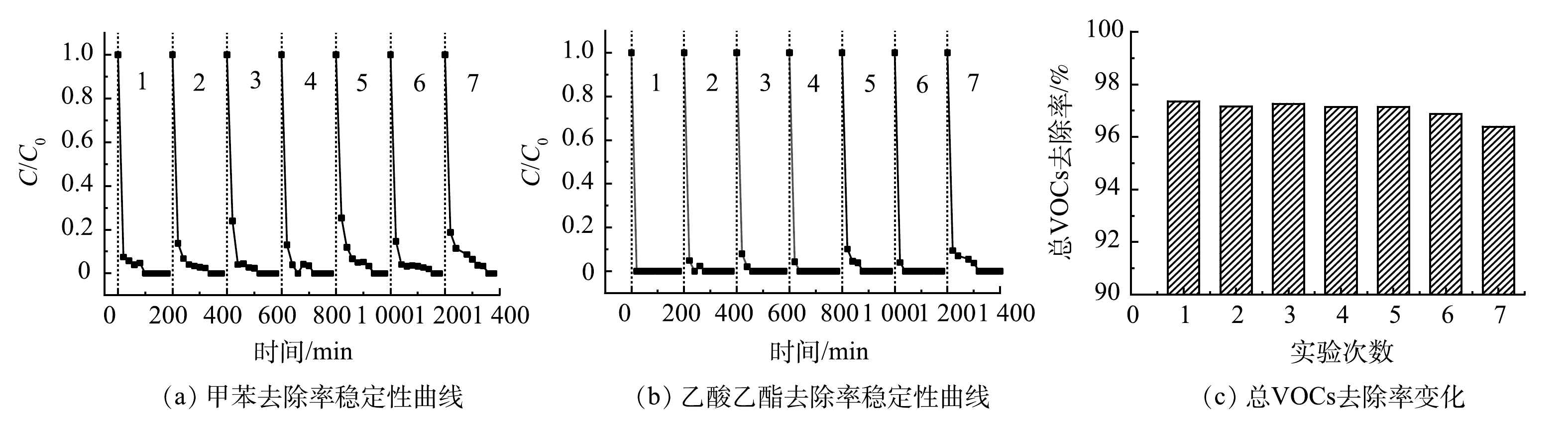
图 8 Pt-CMC/堇青石催化燃烧甲苯和乙酸乙酯稳定性测试结果
Figure 8. Pt-CMC/Cordierite catalytic combustion toluene and ethyl acetate stability test results
Figure
8 ,Table
2 个