-
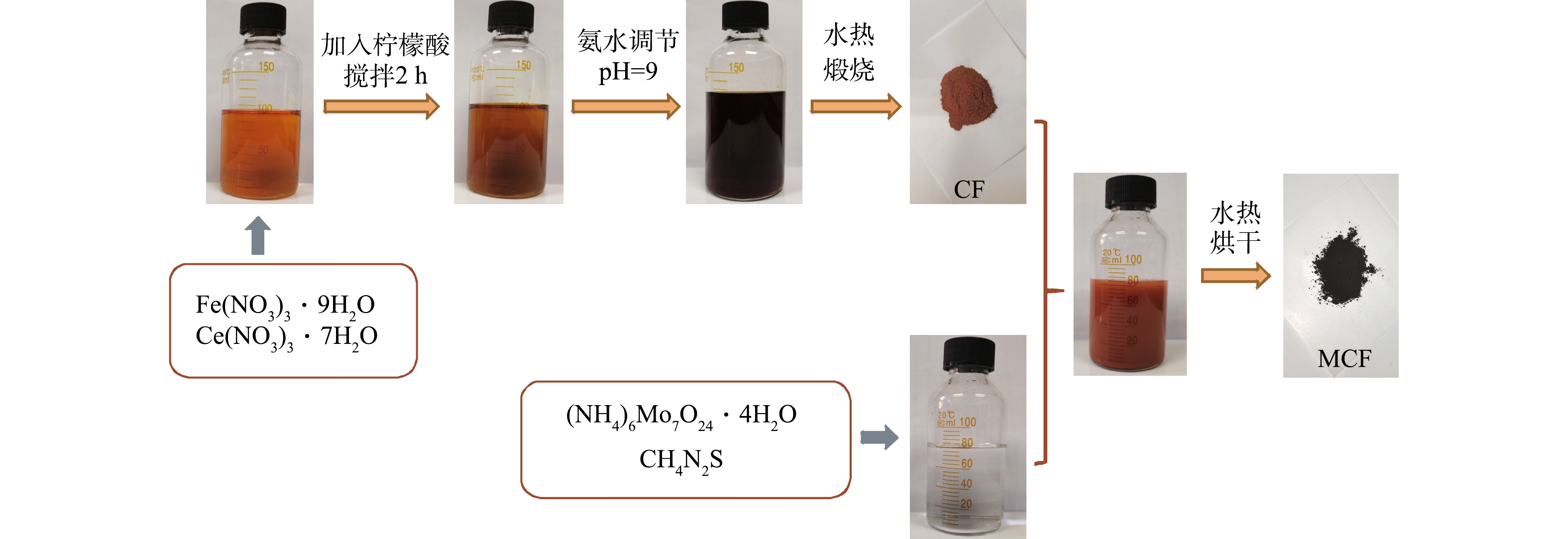
图 1 MCF的制备流程图
Figure 1. Flow chart of MCF preparation
-
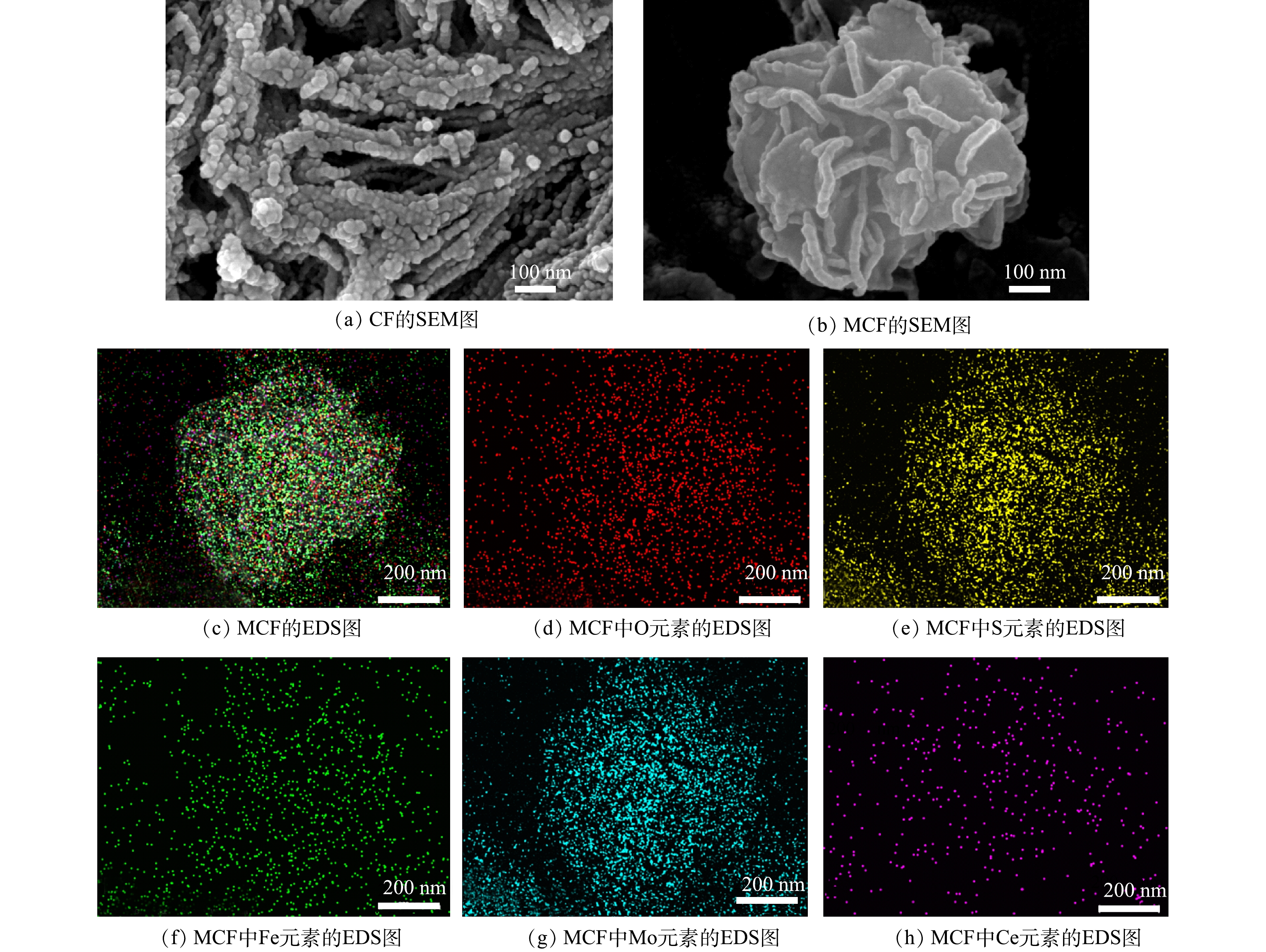
图 2 CF、MCF的SEM图像以及MCF中各元素EDS映射图
Figure 2. SEM images of CF and MCF, EDS-mapping of MCF
-
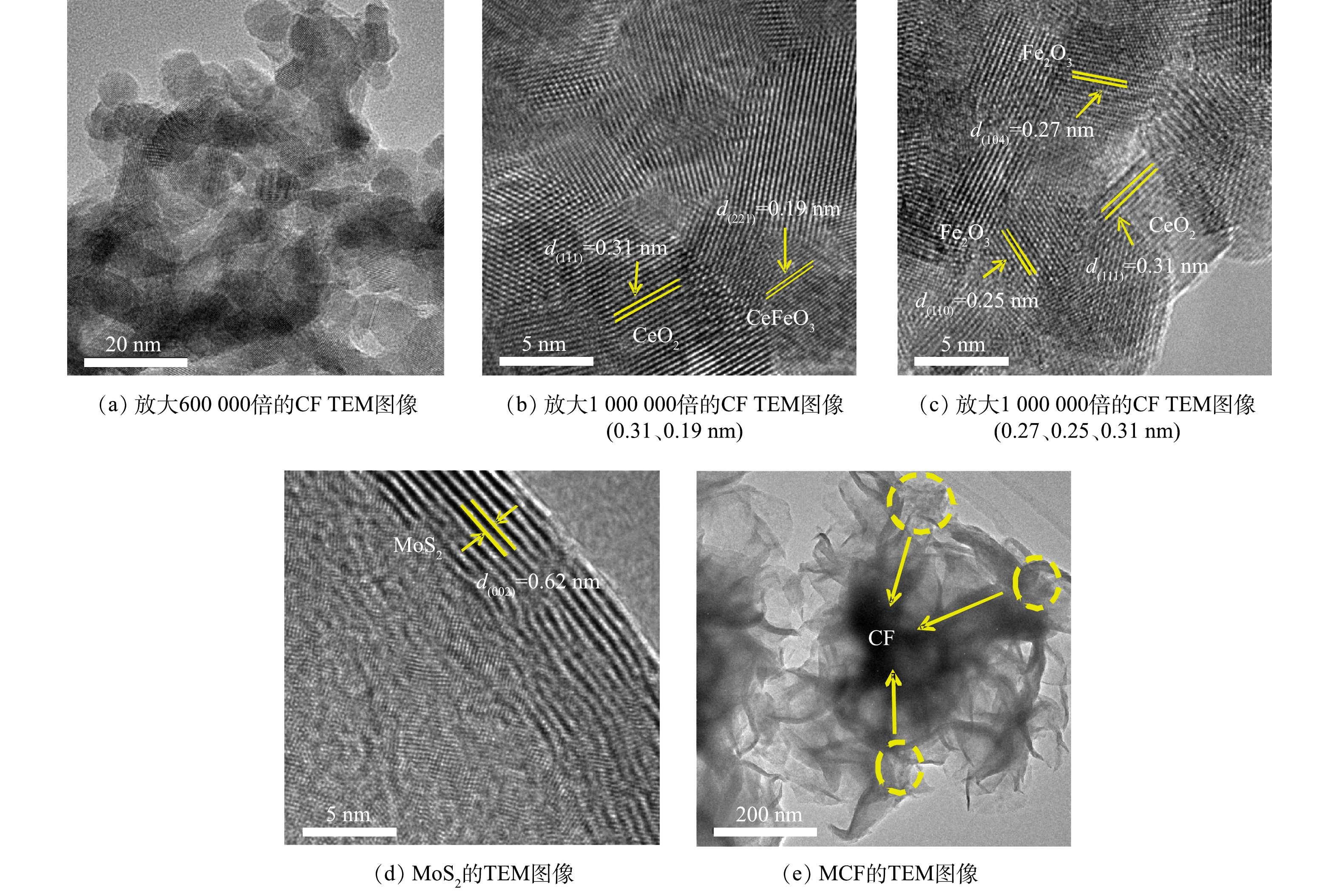
图 3 CF、MoS2和MCF的TEM图像
Figure 3. TEM images of CF、MoS2 and MCF
-
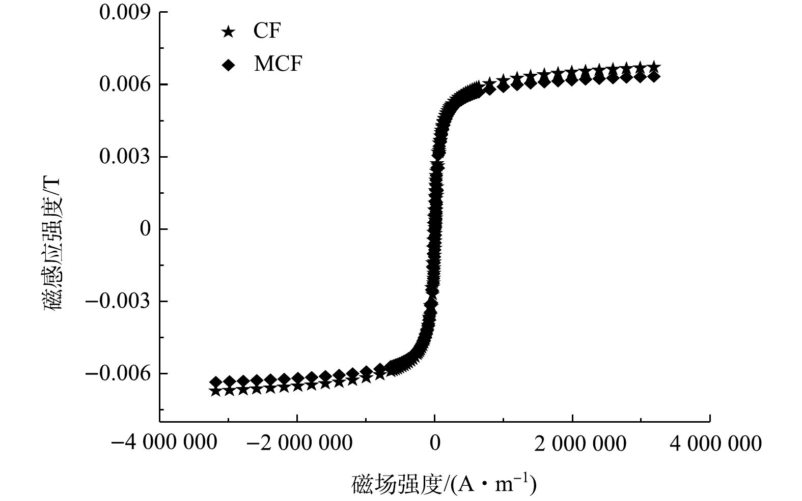
图 4 CF和MCF的磁滞曲线
Figure 4. Hysteresis loop of CF and MCF
-
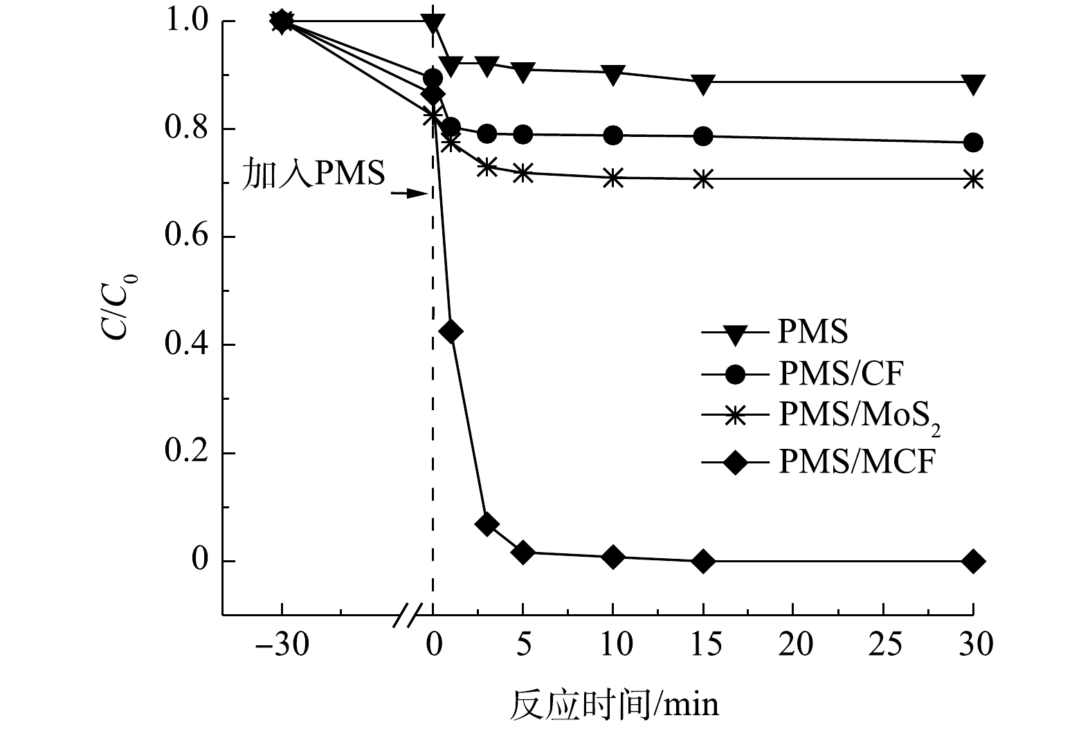
图 5 不同反应体系下AO7的降解情况
Figure 5. Influence of different oxidation systems on AO7 degradation efficiency
-
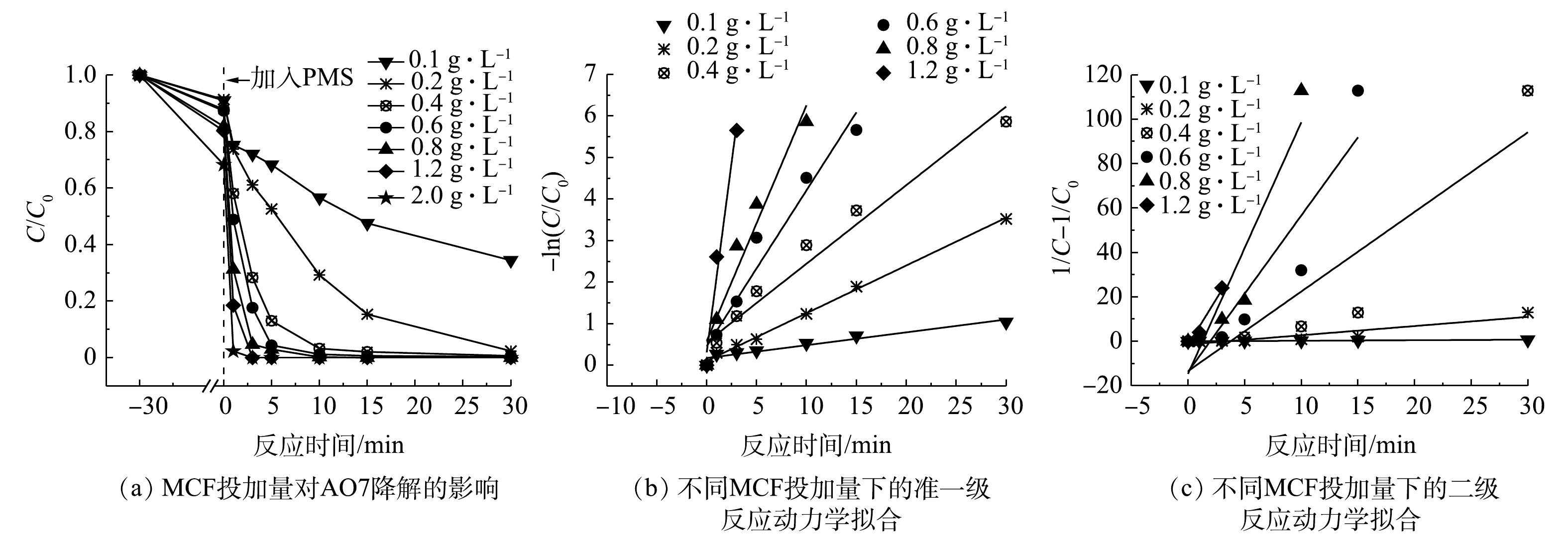
图 6 不同催化剂投加量对AO7降解的影响和动力学拟合结果
Figure 6. Influence of different catalyst dosage on AO7 degradation efficiency and fitting results of reaction kinetics
-
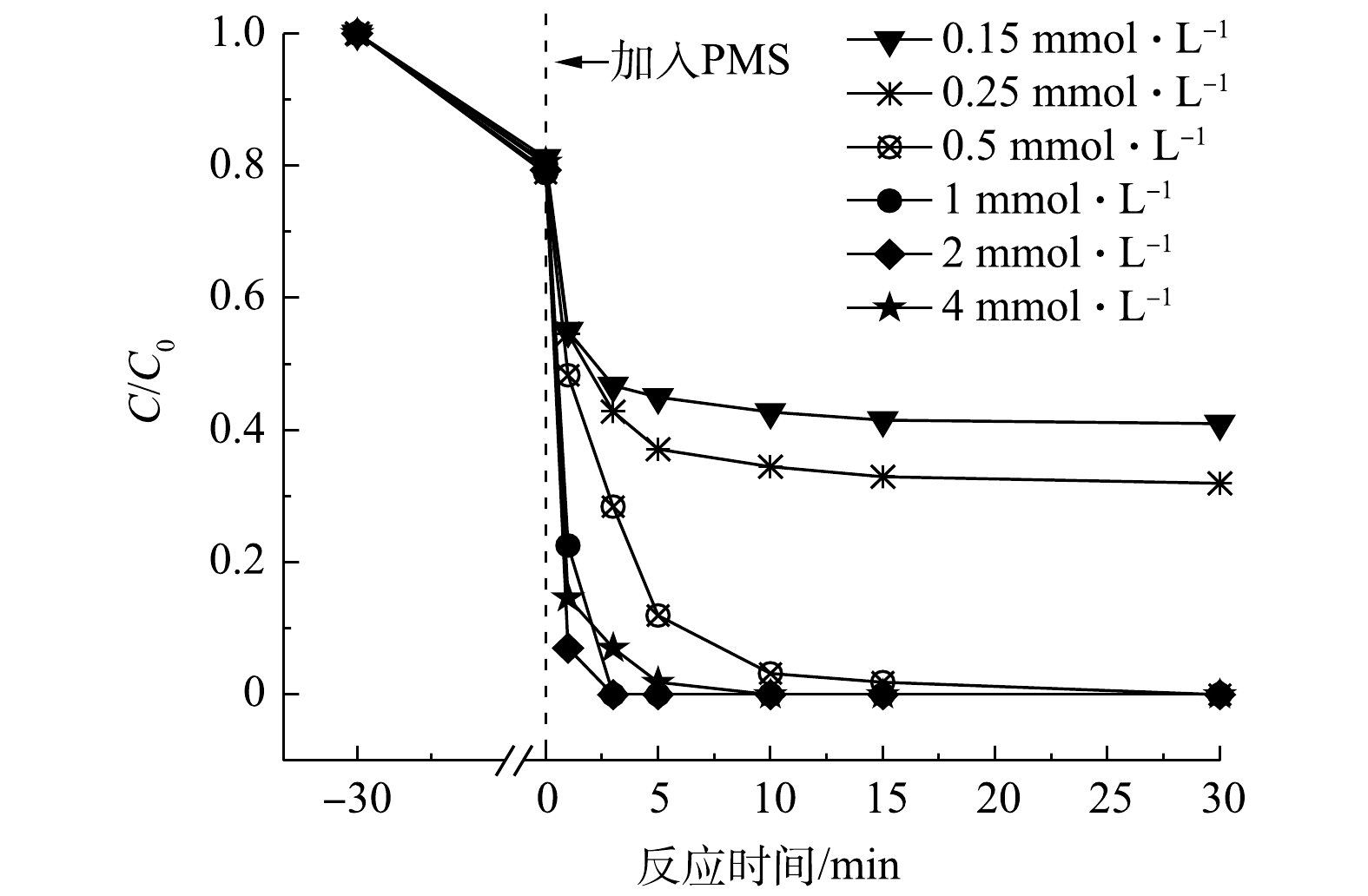
图 7 不同氧化剂浓度对AO7降解的影响
Figure 7. Influence of different oxidation concentration on AO7 degradation
-
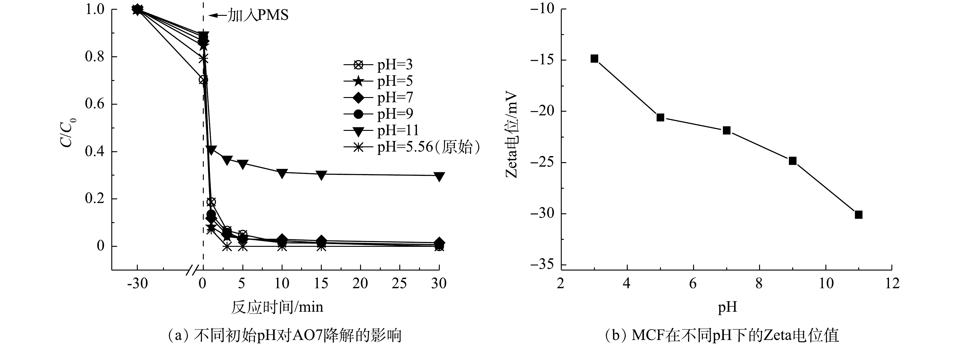
图 8 不同初始pH对AO7降解的影响
Figure 8. Influence of different initial pH on AO7 degradation
-
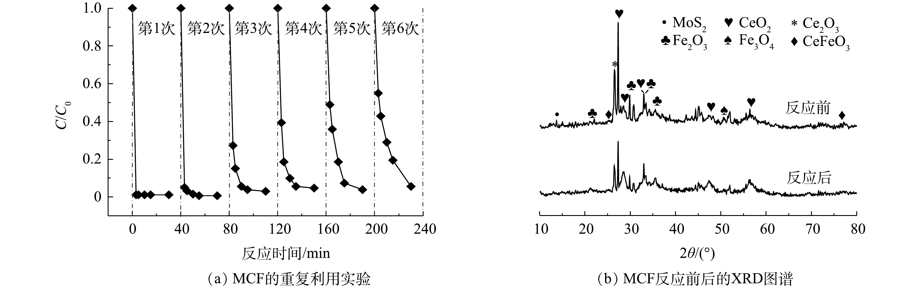
图 9 催化剂MCF稳定性评价
Figure 9. Stability evaluation of MCF
-
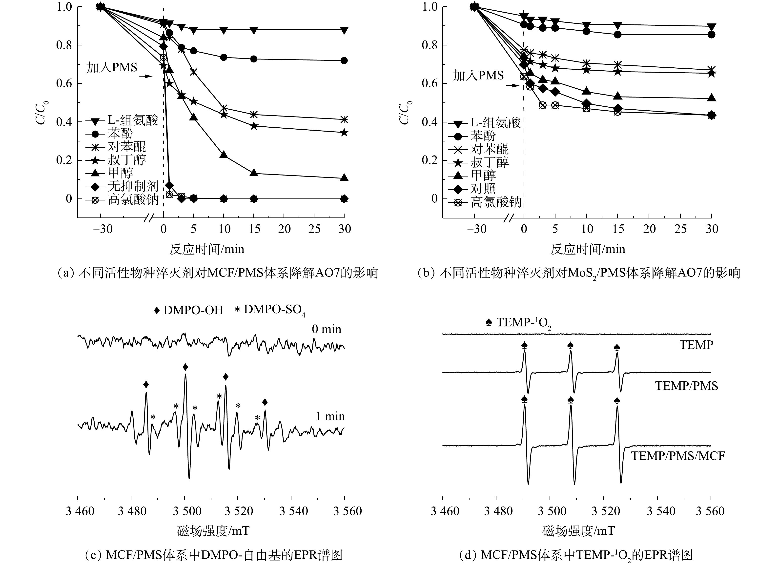
图 10 淬灭剂对降解效果的影响以及MCF/PMS体系中活性物种的捕获
Figure 10. Effect of quenheralation on degradation effect and capture of active species in MCF/PMS system
-

图 11 DMPO-SO4转化为DMPO-OH的可能途径
Figure 11. Possible pathway of DMPO-SO4 transformation to DMPO-OH
-
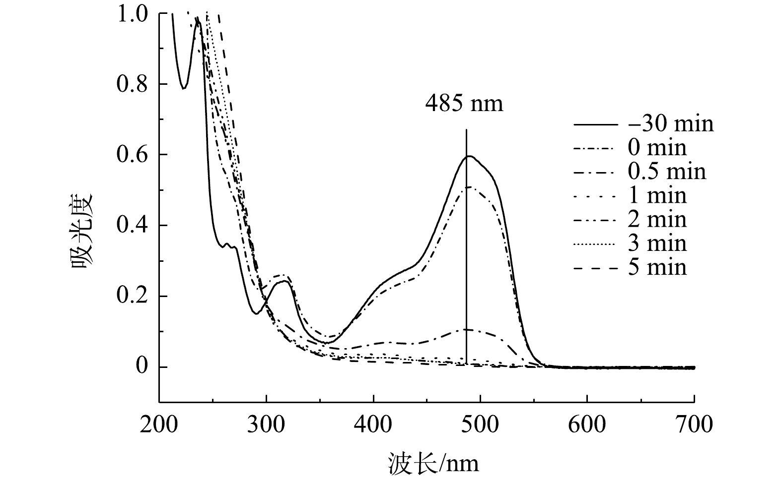
图 12 MCF/PMS体系降解AO7的UV-vis图谱
Figure 12. UV-vis spectra of AO7 degradation by MCF/PMS
-
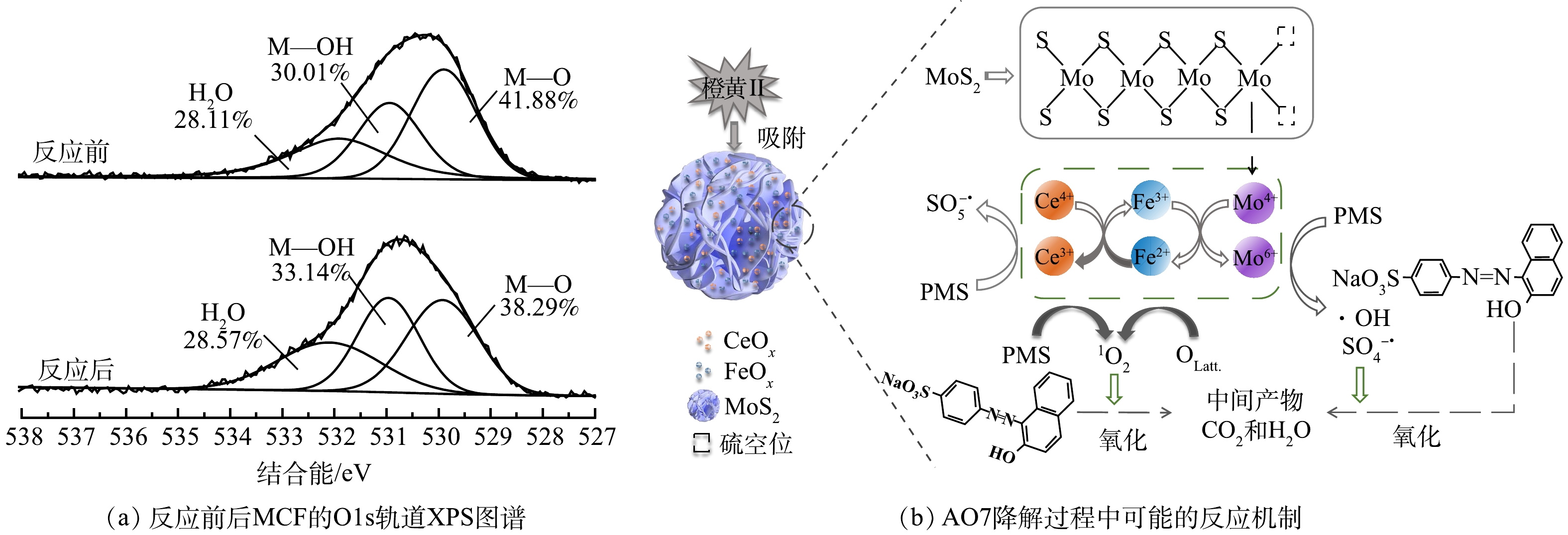
图 13 MCF的O1s轨道谱图和AO7可能的降解机制
Figure 13. O1s spectra of MCF and possible degradation mechanism of AO7
Figure
13 ,Table
2 个