-
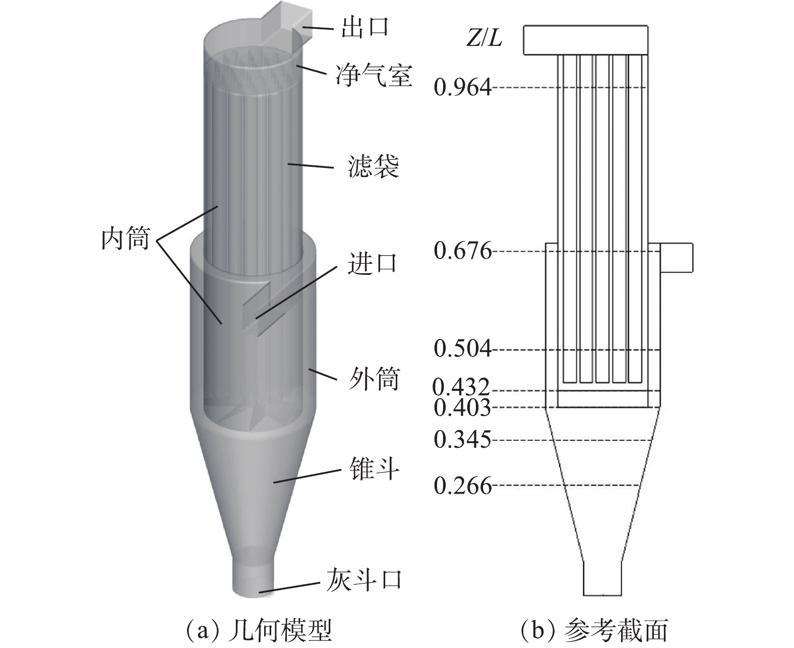
图 1 几何模型和参考截面
Figure 1. Geometric model and reference section
-
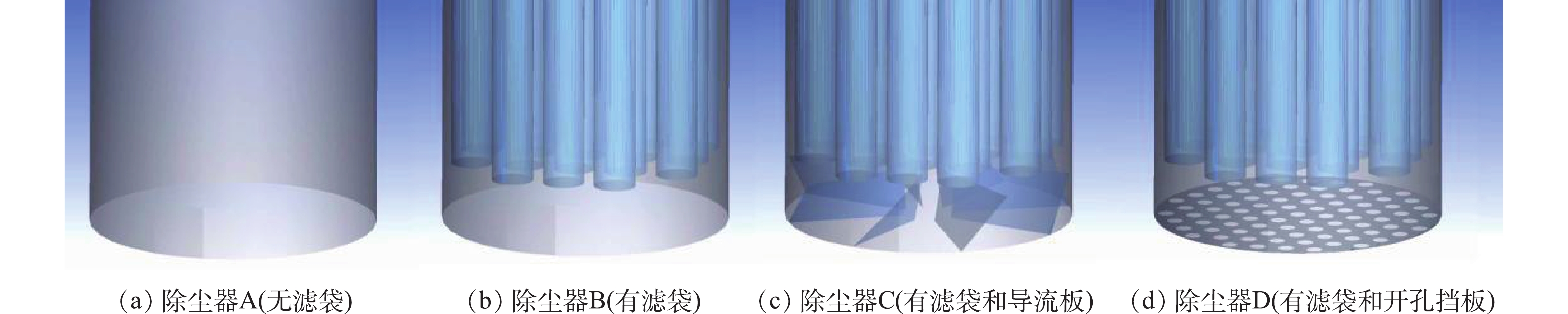
图 2 除尘器不同的内筒结构
Figure 2. Different inner cylinder structure of dust collector
-
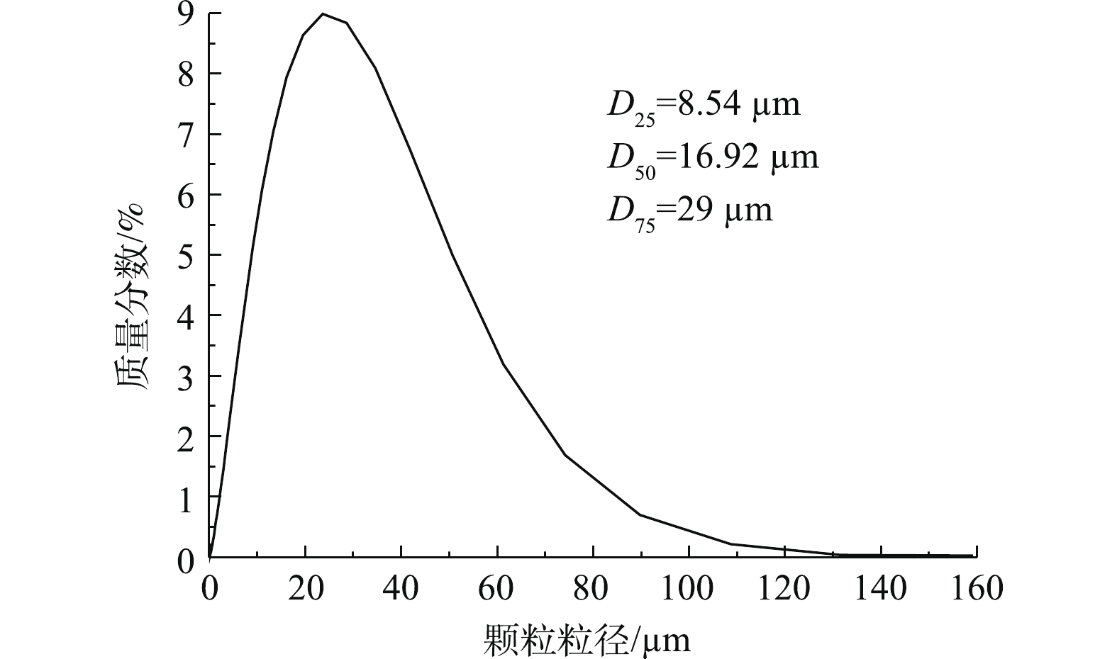
图 3 不同粒径的质量分数
Figure 3. Mass fraction of different particle size
-
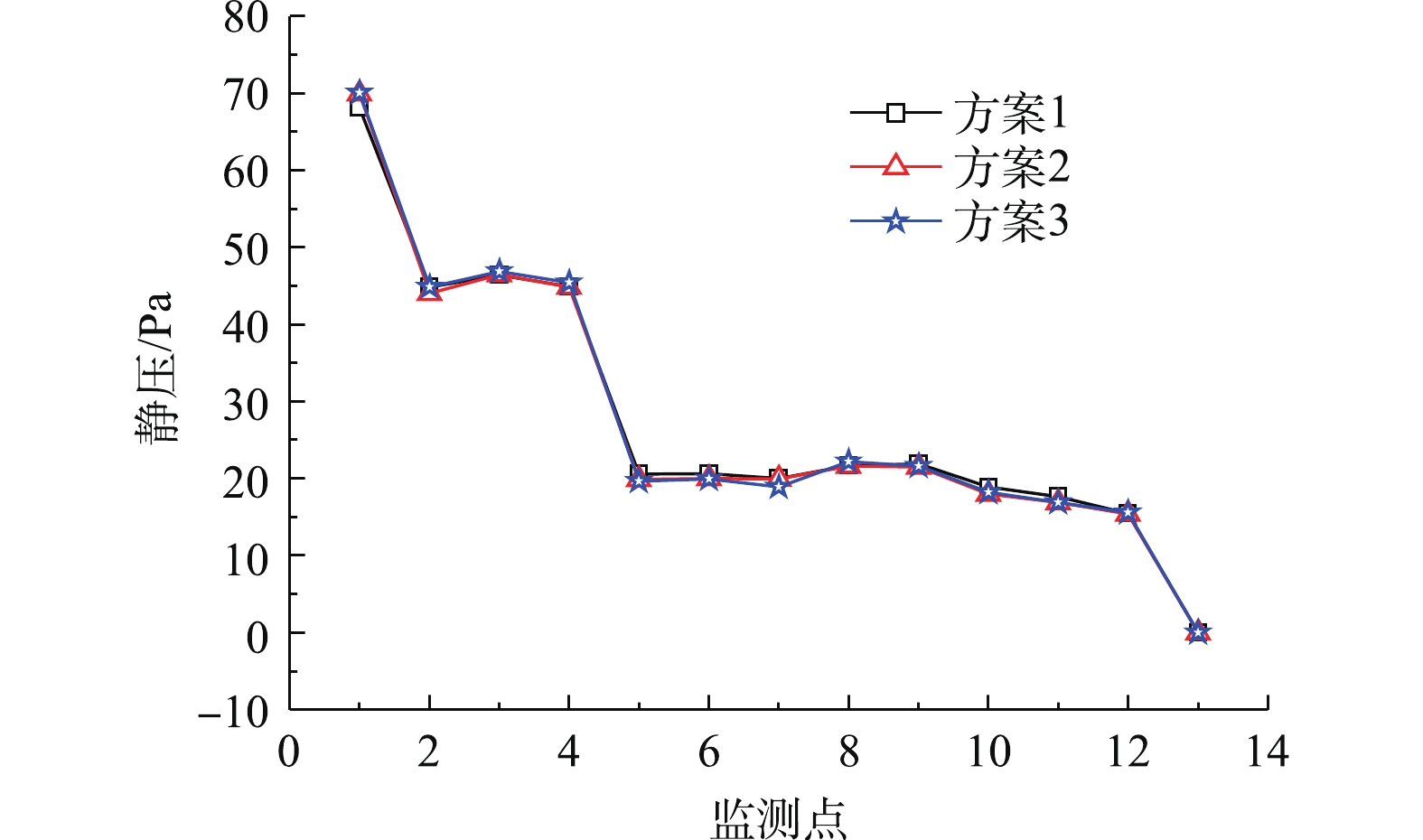
图 4 不同监测点静压的变化
Figure 4. Changes of static pressure at different monitoring points
-

图 5 除尘器的气流流线
Figure 5. Flow trace of dust collector
-
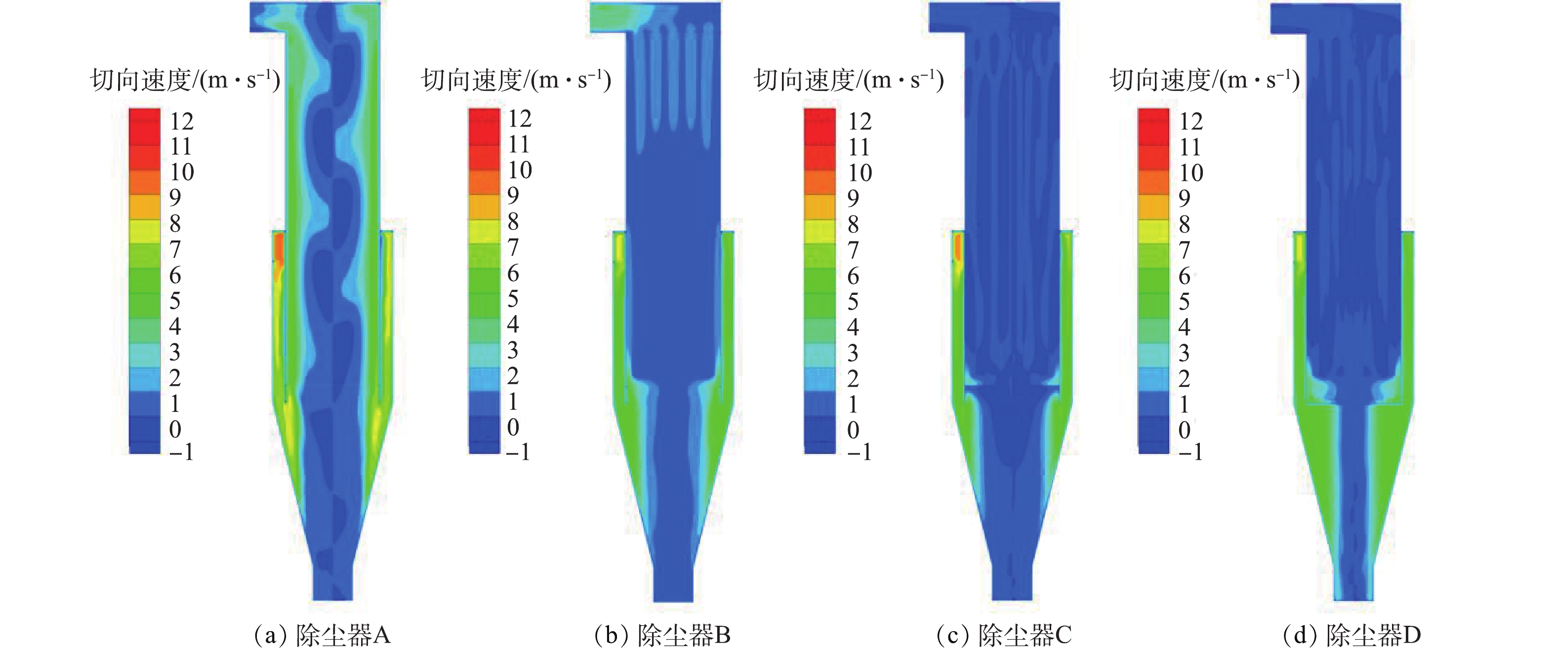
图 6 除尘器在y=0截面的切向速度分布
Figure 6. Tangential velocity distribution of dust collector at y=0 section
-
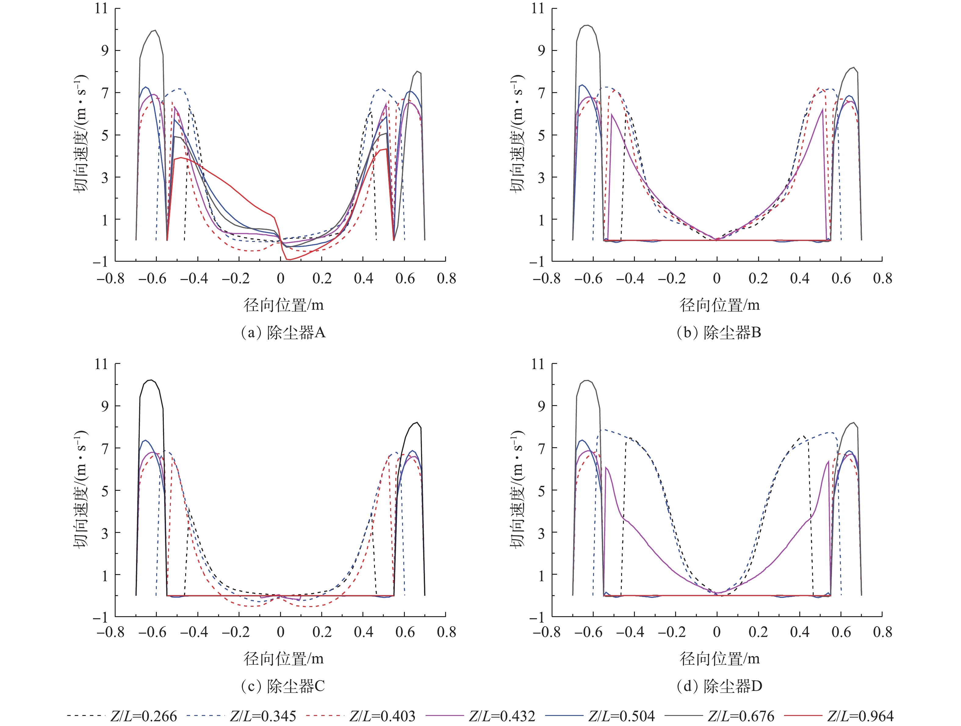
图 7 除尘器在参考截面的切向速度
Figure 7. Tangential velocity of dust collector at the reference section
-
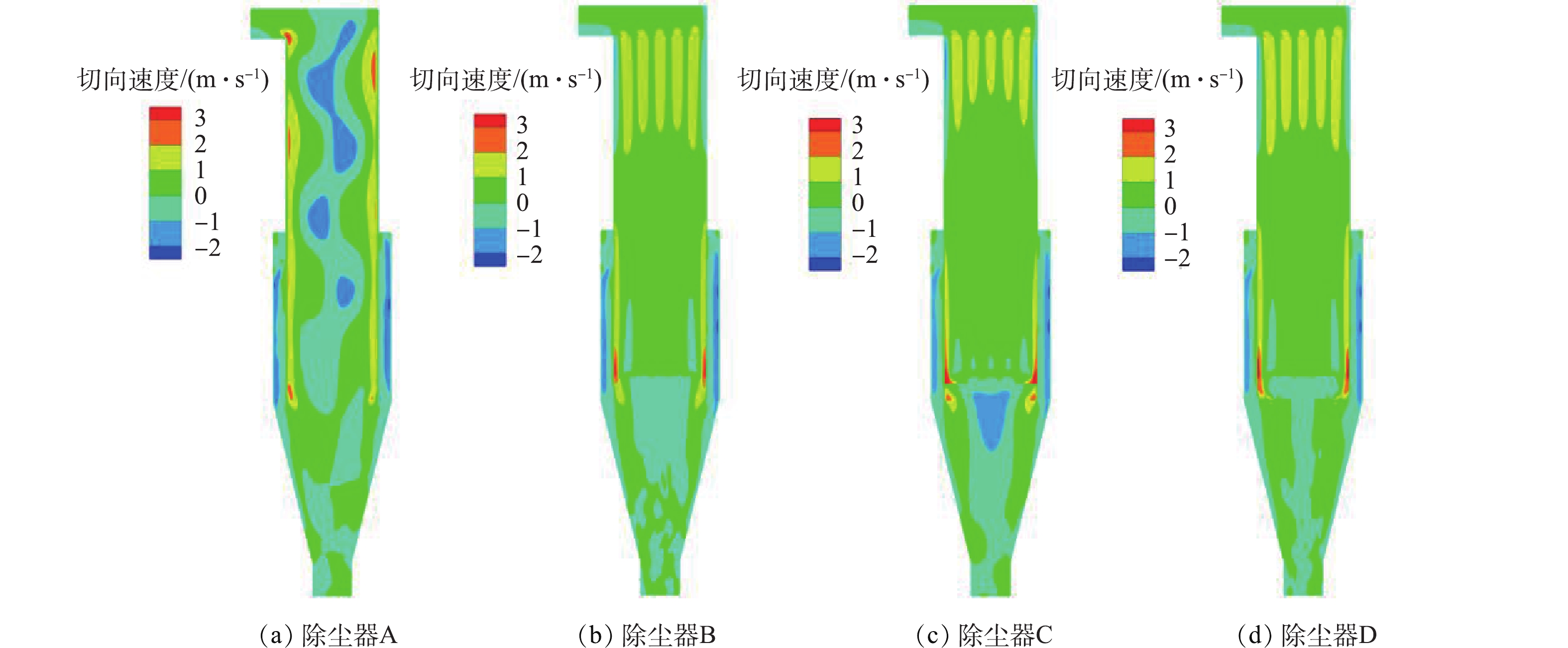
图 8 除尘器在y=0截面的轴向速度分布
Figure 8. Axial velocity distribution of dust collector at y=0 section
-
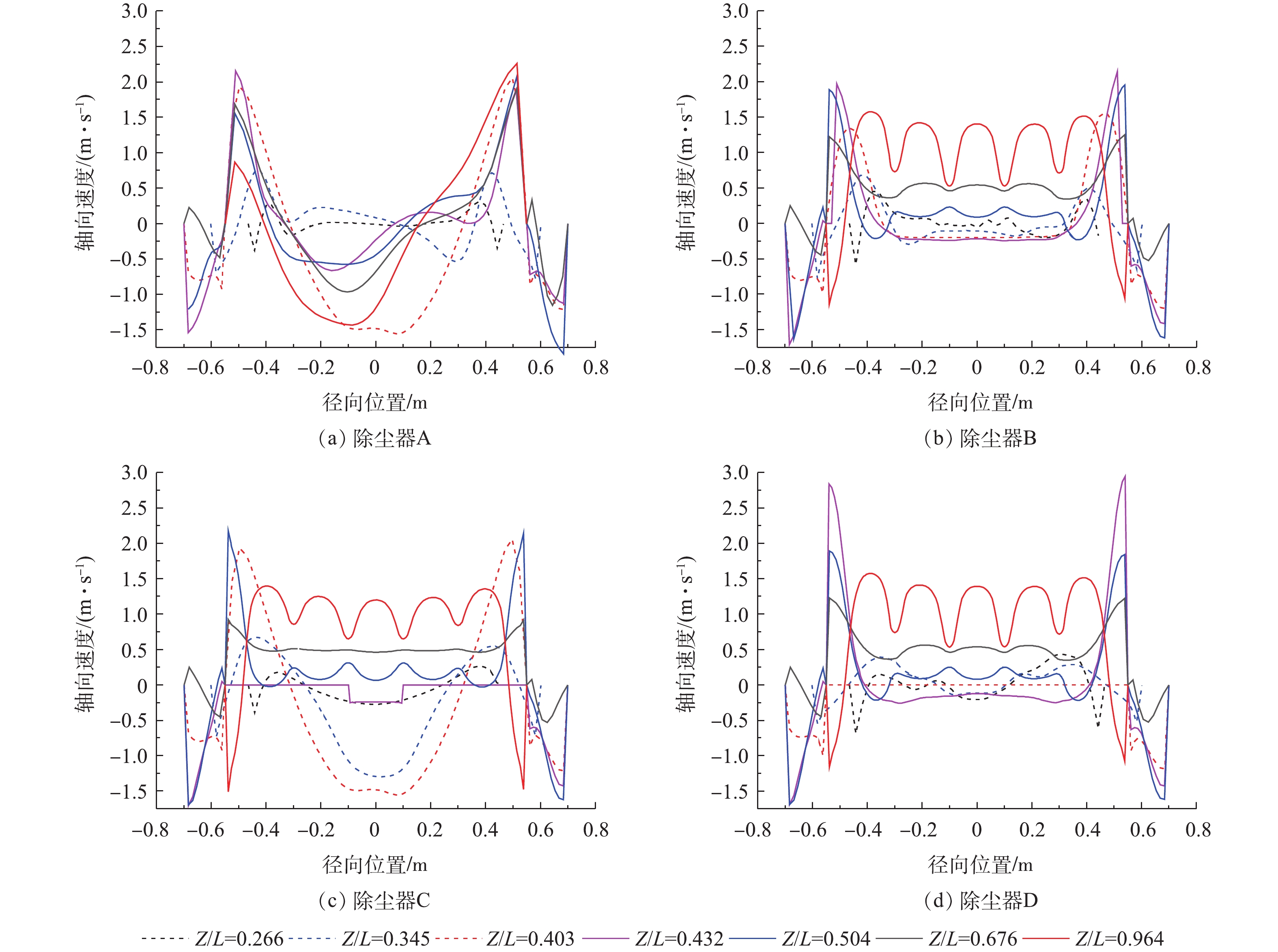
图 9 除尘器在参考截面的轴向速度
Figure 9. Axial velocity of dust collector at the reference section
-

图 10 除尘器在y=0截面和Z/L=0.676截面的静压分布
Figure 10. Static pressure distribution of dust collector at y=0 section and Z/L=0.676 section
-

图 11 除尘器在不同入口风速下的压降
Figure 11. Pressure drop of dust collector at different inlet wind speeds
-
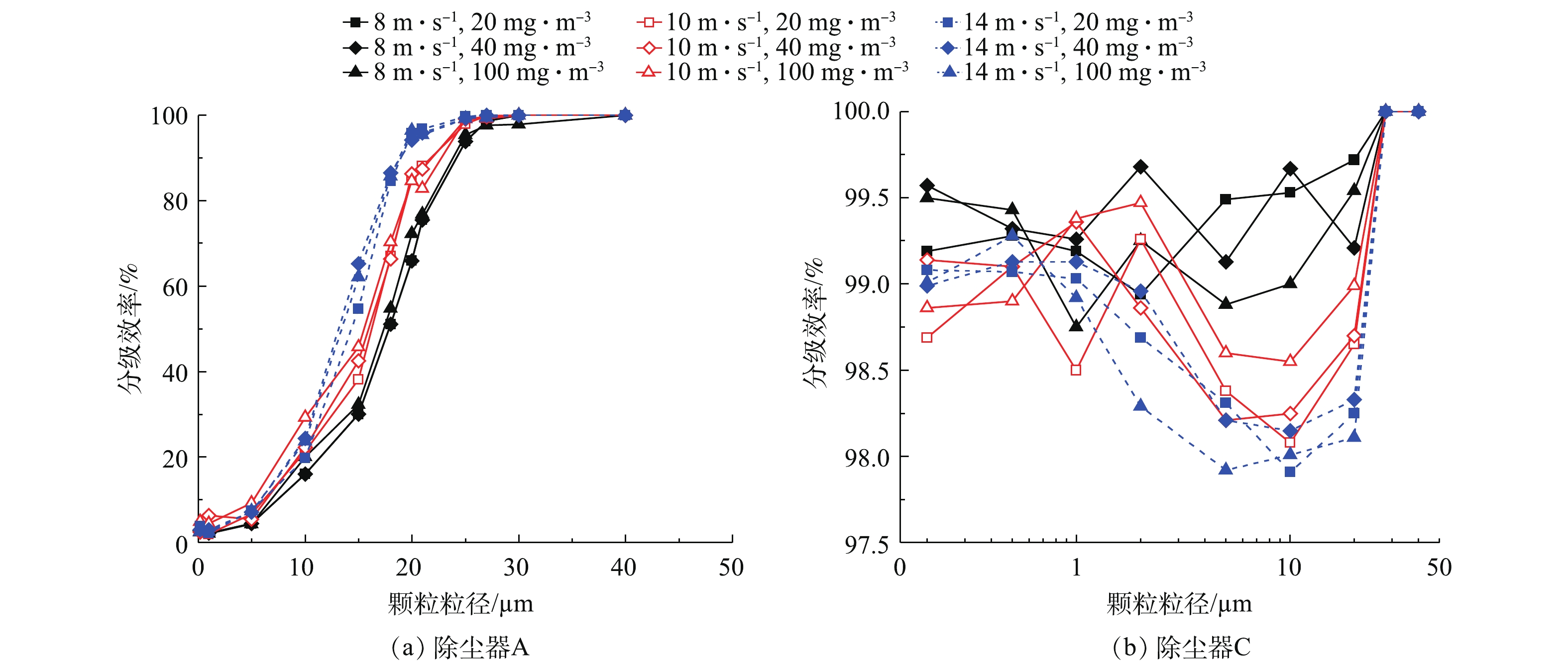
图 12 除尘器A和C的分级效率
Figure 12. Grading efficiency of dust collectors A and C
-
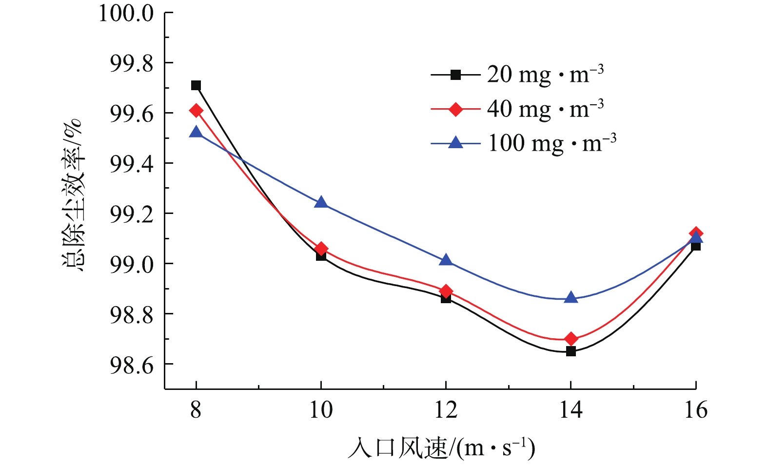
图 13 除尘器C的总除尘效率
Figure 13. Total removal efficiency of dust collector C
Figure
13 ,Table
0 个