-
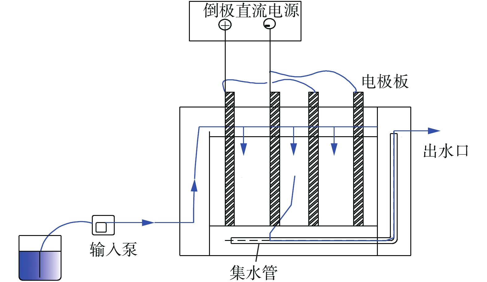
图 1 电絮凝反应装置流程结构示意图
Figure 1. Structure diagram of the flow structure electroflocculation reactor
-
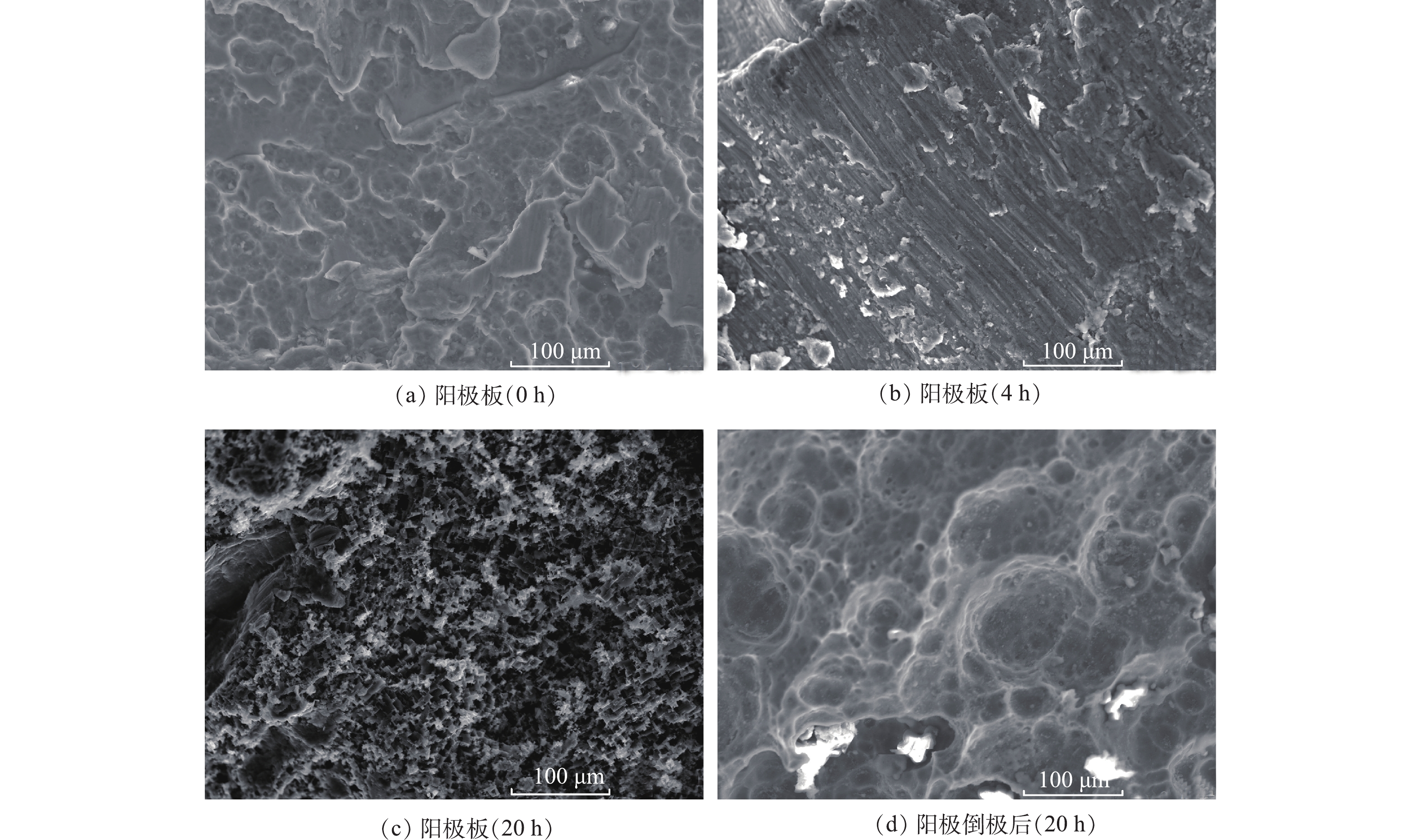
图 2 不同反应时间段阳极板表面SEM图
Figure 2. SEM images of anode electrode surface during different reaction time intervals
-
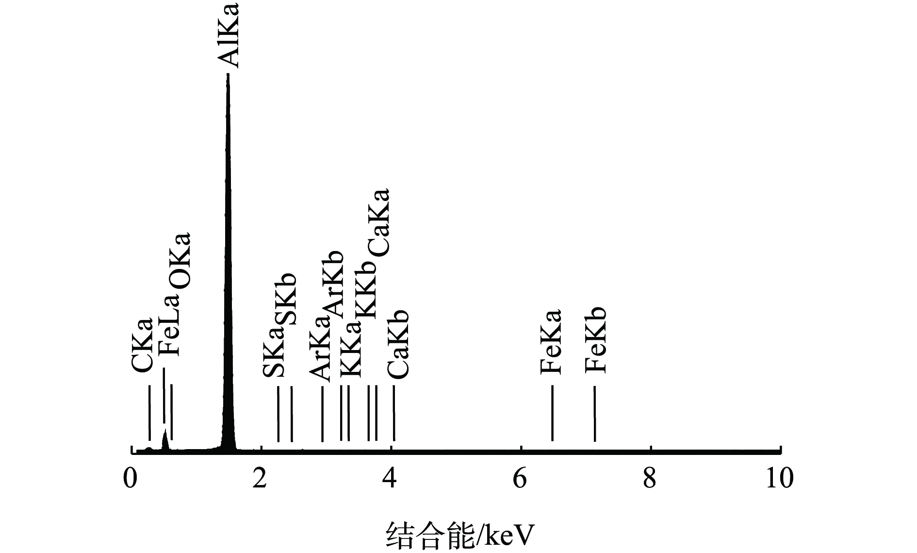
图 3 反应12 h阴极板的EDS图谱
Figure 3. EDS spectrum of the cathode electrode after12 hours of reaction
-
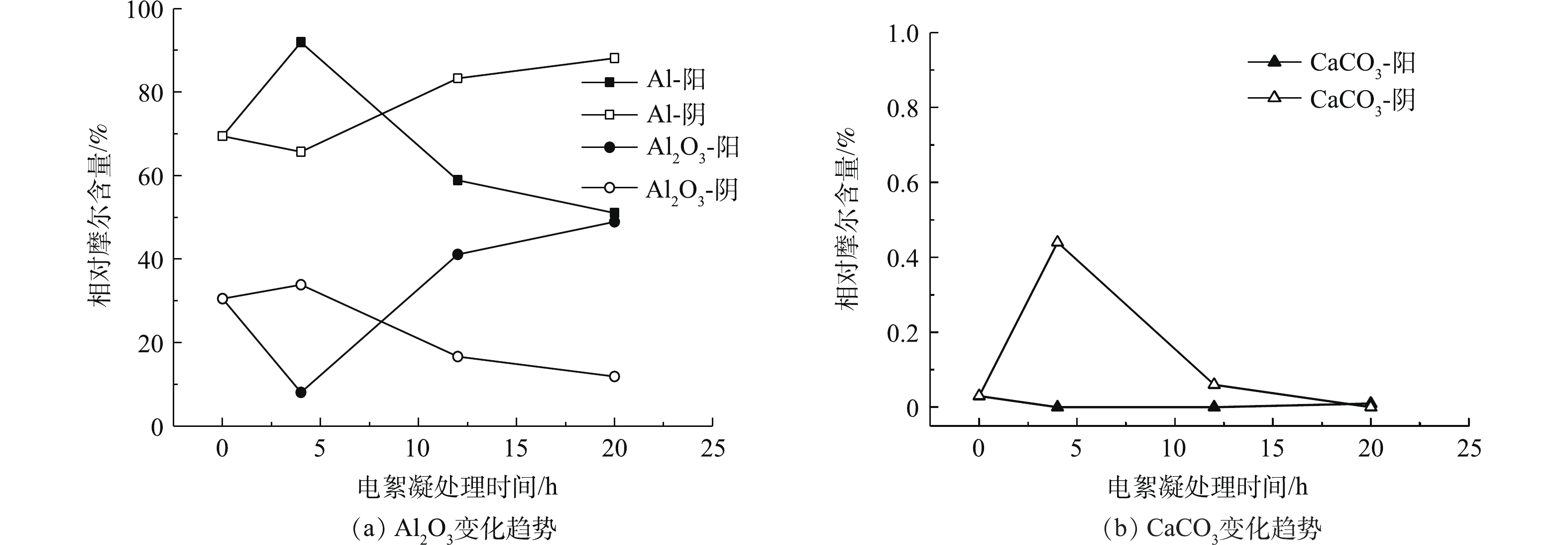
图 4 倒极前阴-阳极板表面钝化层成分随电絮凝时间的变化趋势
Figure 4. Variation trends of composition of surface passivation layer in the cathode-anode electrodes withelectricflocculation time before reversing electrodes
-
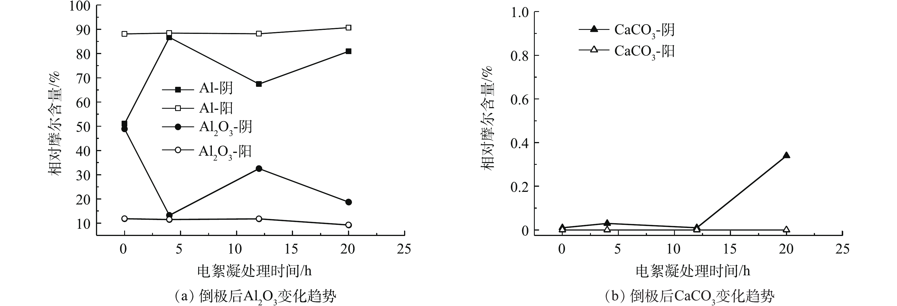
图 5 倒极后阴-阳极板表面钝化层成分随电絮凝时间的变化趋势
Figure 5. Variation trends of composition of surface passivation layer in the cathode-anode electrodes withelectricflocculation time after reversing electrodes
Figure
5 ,Table
1 个